My trusty 20M GP antenna, is a much-loved and proven favourite for operations away from the home QTH. Recent experience has made clear however that It’s not ideal for POTA, SOTA and other short term /P activations. It’s relatively heavy at about 2kgs, and it takes about 15 minutes to set up. Of course, it’s also a single band antenna. That, above all else is a bit limiting.
In my many forays into the world of antennas over the years, I’d occasionally come across the “End Fed Half Wave” antenna – EFHW – but I didn’t pay much attention. I finally did take notice when I went looking for a POTA antenna that would perform some way efficiently, while also being light-weight, multi-band and easy to deploy.
When I started looking for an alternative to the 20M GP, I quickly learned that the EFHW is a favourite among POTA and SOTA operators. Despite the wisdom of the herd, I was a bit skeptical of the claims being made for the EFHW. If I’m honest, it almost sounded too good to be true. Nonetheless, given how easy an EFHW is to make, I reckoned I’d nothing to lose by putting one together and trying it out.
I’ll summarise making one first and then talk about my early experiences with using it after. Spoiler, I’m very impressed.

EFHW Basics:
- An EFHW antenna is a half wavelength long on the lowest band of operation. In other words, it’s a half wave dipole on that band.
- Unlike the most common dipole variant however, an EFHW is not fed in the middle but instead it’s fed at one of the ends.
- Feeding a dipole at one end and not in the middle, means a much higher impedence at the feed point. To match an EFHW to a 50ohm transmitter, a 49:1 un-un is used at the feedpoint.
- An EFHW needs some sort of counterpoise or connection to earth. It doesn’t need very much at all – the wisdom is that a counterpoise a mere 0.05 wavelength long on the fundamental frequency, or a short stake into the ground, is sufficient. The antenna does need something however. If you don’t provide a counterpoise, it’ll make use of whatever it can find electrically e.g. the feedline coax shield. If there really is no counterpoise or earth available, then the antenna won’t work. It’s better to have an explicit counterpoise or earth connection as otherwise, you may find the antenna is inconsistent from a tuning perspective in use, and it could result in “RF in the shack” issues at the rig. That’s not something you want, particularly if you’re running higher power.
- An EFHW will resonate on even and odd harmonics of it’s fundamental frequency. As such, it can be used as a multiband antenna.
- If using an EFHW as a multiband antenna, adding some capacitance at the feed point can help with resonance on the higher bands.
- Because an EFHW is fed at one end, it’s an easy antenna to get up in the air, that’s a big part of its’ attraction. An EFHW can be put up as a horizontal wire, as a vertical wire, as a sloper or as an upside down L. I’m intentionally not using the term “inverted L”, to avoid confusion with that antenna type. The EFHW if put up as an upside down L, looks physically like an inverted L but it works very differently.
Design Criteria for my EFHW Antenna:
- Max Transmit Power: 5W.
- Bands: 40M, 20M, 15M and 10M.
- Insulated radiating wire so it can be run directly over tree limbs, through bushes etc.
- Compatible with my existing “/T” and “/P” equipment, so a PL-259 connector at the antenna feedpoint.
- Lightweight and compact.
- Weather proof.
- Low profile – no bright orange wire or other “glizty” parts that might draw attention.
Parts List:
- A length of insulated wire for the antenna wire, that’s a half wavelength long on the lowest frequency you wish to operate on. I went for 40M, so I used circa 22 metres (67′) of wire. I used one strand of twin field telephone wire. That stuff is very strong, light and low profile. It’s also almost impossible to tangle up.
- A second length of wire for the counterpoise. Make that about 0.05 wavelength long on the lowest frequency you wish to operate on. For 40M, that’s 2 metres (3.3′). Alternativley, make a ground rod. I went with a ground rod made from a 250mm (10″) length of aluminium rod I had lying around.
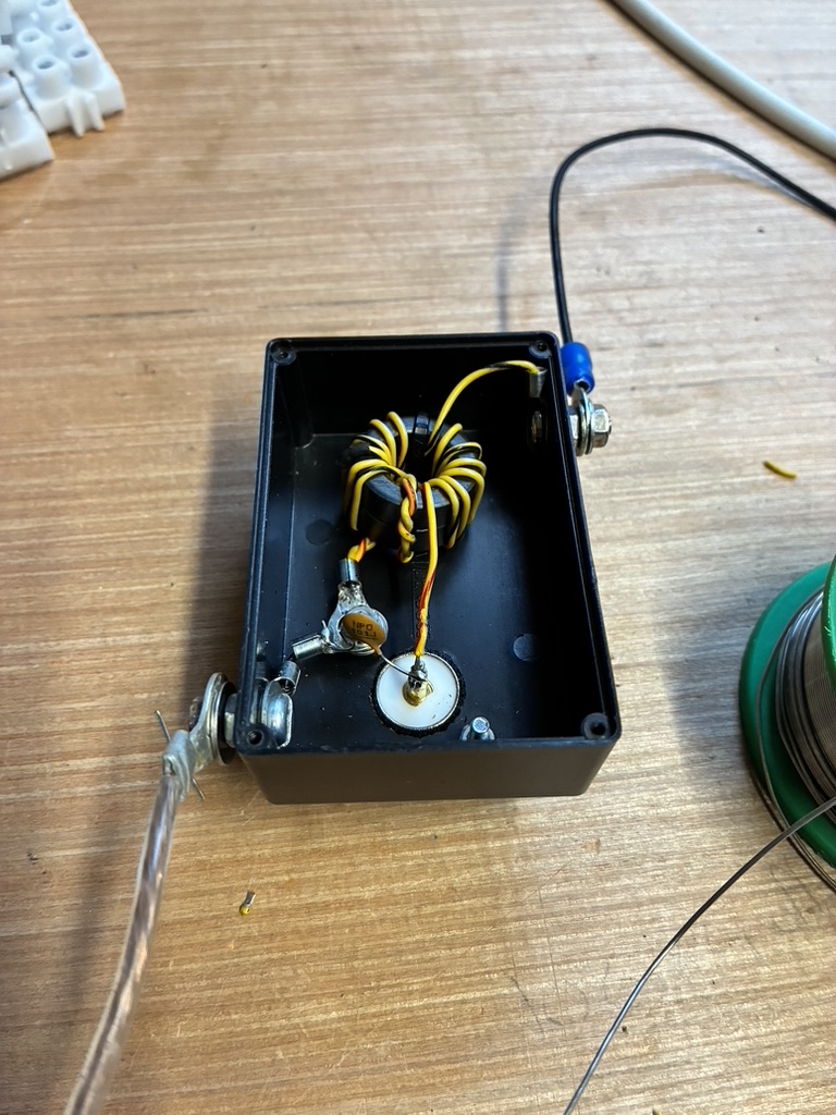
- Type 43 toroid(s). How many and how big they are will depend on how much power you wish to run. As I was only building for 5W, I used FT23-43 toroids. I might have gotten away with even smaller. I used two of them, glued together with superglue. At 5W, one toroid would almost certainly been enough but seeing as how I had two to hand, I decided to take a “belts & braces” approach.
- A 100pF capacitor. This is optional but helps the antenna to resonate and in a useful place, on the higher bands i.e. 15M and 10M in the case of my antenna. Again as the antenna is only for QRP use, I was able to use a 50V rated capacitor from the junk box. For higher powers, you’ll want to use a higher rated capacitor.
- A suitable enclosure for the feedpoint connections. I used a black plastic box with a screw on lid measuring about 80mm (3″) x 40mm (1.5″) x 20mm (0.8″). Sometimes with ferrite based components, you want to avoid using a metal enclosure as it could alter the performance characteristics of that component. I don’t think this is one of those situations but I’m open to correction on that…
- A panel mount SO239 for the coax connection.
- A means to connect the antenna wire and the counterpoise/ground. I used M5 nuts & bolts and suitable eyes soldered onto the antenna wire and counterpoise/ground wire.
Making the Antenna:
- Cut the radiating wire a bit longer than calculated, to have a bit extra for tuning purposes. Cut the counterpoise and/or make up the ground rod.
- Drill required holes in the feedpoint box.
- Mount the coax connector.
- Wind the 49:1 un-un. This is the only bit that requires some care. Rather than repeat excellent guidance that’s already on the internet by other kind souls, take a look at e.g. MM0ZIF’s instructions, Gordon Gibby’s instructions or KM1NDY’s instructions (thanks folks!).
- Connect the antenna wire to the secondary wire of the un-un, one end of the primary wire pair to the counterpoist/ground and the remaining primary wire to the antenna feed point.
- Solder the 100pF capacitor across the antenna feedpoint and the counterpoise/ground point.
- Box it up. Tune it up. Have fun!
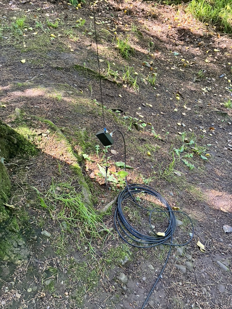
So, what’s the EFHW like in use? I humbly concede my arrogance & stupidity in not accepting herd wisdom; the EFHW is a wonderful antenna for /P activities of all sorts and is a surprisingly effective performer. Albeit I’ve only two POTA activiations with it to date IE-0043 and IE-0246, it’s very apparent that this antenna is a keeper. The EFHW is one of those antennas that just wants to work. It’s very tolerant of how it’s mounted and it takes mere moments to get it airborne. So far, I’ve used it only in an upside down L configuration. I’ll set it up vertically and horizontally in due course but I don’t expect any change in performance.
I’m so impressed with the EFHW, that I’m building two more; a 100W 40M-10M version for “/T” operations using 3 FT37-43 toroids for the 49:1 un-un, and a 200W 80-10M version for permanent installation at home as a secondary/backup antenna. For that version I’ll be using 2 FT50-43 toroids for the un-un.
Once I’ve more use experience with all three EFHW antennas, I’ll update this post.